
Precast Infrastructure Moulds
Cable Trench Cover Slab Mould: Seating Ledge, Joint Clearance and Production Guide
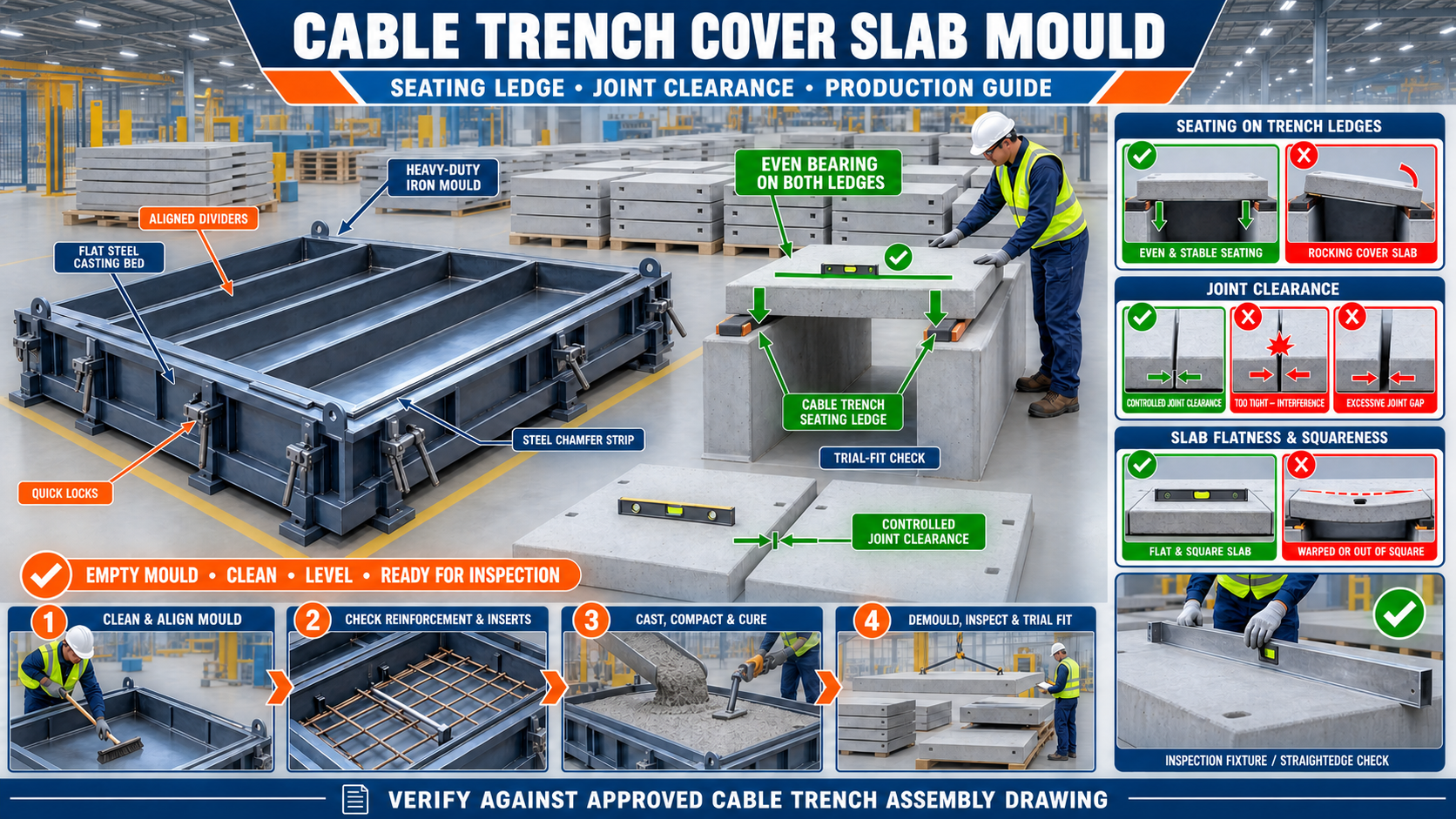
A cable trench cover slab must fit securely on the supporting ledges of a precast cable trench while remaining practical to install and remove. Incorrect slab dimensions, uneven seating faces or uncontrolled joint clearance can cause rocking, edge damage and installation problems. This guide explains iron cover-slab mould setup, casting and fit inspection.
By Paras Steel Industries ·
Cable Trench Cover Slab Mould: Seating Ledge, Joint Clearance and Production Guide
Cable Trench Cover Slab Mould: Seating Ledge, Joint Clearance and Production Guide
Precast cable trenches provide protected routes for electrical, communication and control cables. These trench units are commonly closed using removable precast concrete cover slabs.
A cover slab must match the supporting ledges of the trench. It should sit evenly without excessive movement, rocking or interference. This depends on the dimensional accuracy of both the cable trench mould and the cover slab mould.
A heavy-duty iron cover slab mould helps manufacturers produce repeatable slab dimensions, clean edges and consistent seating surfaces.
What Is a Cable Trench Cover Slab?
A cable trench cover slab is a precast concrete component positioned across the open top of a cable trench.
Depending on the project design, it may provide:
• Cable protection • Controlled access for inspection • A closed trench top • Protection from debris • A defined walking or service surface where specifically designed • Segmented removal for maintenance
The required slab size, reinforcement and duty should always follow the approved project drawing.
What Is a Cable Trench Cover Slab Mould?
A cover slab mould is an iron or steel form used to cast the slab’s dimensions, edge profile and surface finish.
A typical mould may include:
• Heavy-duty steel base plate • Side shutters • End shutters • Structural stiffeners • Quick locks or clamps • Chamfer strips • Lifting-insert fixtures • Recess formers • Dividers for multi-slab production • Alignment stops • Mould-support frame
The mould may produce one slab or multiple slabs in each casting cycle, depending on the approved design.
Relationship Between Trench and Cover Slab
The trench and cover slab function as a matching system.
The trench mould controls:
• External trench dimensions • Internal cable space • Wall thickness • Supporting ledge position • Top opening • Joint details
The cover slab mould controls:
• Slab length • Slab width • Slab thickness • Edge profile • Seating contact • Insert or lifting-detail position
Both moulds should be checked against the same approved assembly drawing.
What Is a Seating Ledge?
A seating ledge is the horizontal supporting surface formed near the top of a cable trench wall. The cover slab rests on this ledge.
A reliable seating ledge should be:
• Continuous where specified • Dimensionally consistent • Free from major concrete fins • Properly aligned across both trench walls • Compatible with the cover-slab bearing area • Checked for level and flatness
If the two ledges are at different levels, the cover slab may rock or carry load unevenly.
Why Seating-Ledge Accuracy Is Important
Accurate seating ledges help provide:
• Stable cover-slab support • Reduced rocking • Consistent top alignment • Better load distribution • Reduced edge damage • Easier installation • Easier slab removal • Cleaner trench appearance • Reduced repair work
The supporting condition should be checked before modifying the cover slab.
What Is Joint Clearance?
Joint clearance is the designed space between:
• Adjacent cover slabs • A cover slab and the trench end • A cover slab and adjoining structure • The slab edge and any locating profile
Suitable clearance allows for practical installation, removal and permitted dimensional variation.
Clearance that is too small can cause interference. Excessive clearance can create movement, visible gaps and poor alignment.
The required clearance must come from the approved project drawing.
Problems Caused by Incorrect Clearance
Insufficient Clearance
This may cause:
• Slabs jamming during installation • Edge chipping • Difficulty during removal • Forced fitting • Damage to trench walls • Uneven slab positioning
Excessive Clearance
This may cause:
• Side movement • Irregular joint lines • Large visible gaps • Poor appearance • Debris entry • Unstable positioning where the design does not provide restraint
Clearance should never be selected only by visual judgement.
Types of Cover Slab Moulds
Single-Cavity Mould
A single-cavity mould produces one slab per casting cycle.
It may suit:
• Large slabs • Custom project dimensions • Low-volume production • Frequent profile changes
Multi-Cavity Mould
A multi-cavity mould uses dividers to cast several slabs in one cycle.
It may provide:
• Higher production output • Consistent dimensions • Better batch planning • Reduced setup repetition
All dividers must remain accurately aligned.
Fixed Mould
Fixed shutters can offer repeatability for a single slab design.
Adjustable Mould
An adjustable system may support compatible slab sizes using movable end shutters or dividers.
Every size change should be verified against the production drawing.
Heavy-Duty Iron Mould Construction
A reliable cover slab mould requires sufficient stiffness and dimensional stability.
Important construction features may include:
• Flat steel casting plate • Rigid side shutters • Structural channels • Adequate cross supports • Strong corner joints • Accurate locating stops • Accessible locking points • Smooth forming surfaces • Replaceable profile inserts where required • Stable base frame
The required plate and stiffener arrangement depends on slab dimensions and production conditions.
Preparing the Mould Before Casting
Before mould assembly:
• Clean the forming surfaces • Remove old concrete and slurry • Inspect the base plate • Check side and end shutters • Inspect dividers • Check chamfer strips • Verify locating pins and stops • Inspect locks and clamps • Confirm the mould is level • Review the slab drawing
Do not cast on a mould bed that is visibly twisted or inadequately supported.
Establishing a Fixed Datum
All mould dimensions should be checked from a verified reference.
Possible datums include:
• Mould centreline • Fixed side shutter • Machined base-frame stop • Verified corner • Approved divider location
Avoid using hardened concrete deposits or damaged plate edges as measurement references.
Checking Cover Slab Length and Width
Measure the mould cavity at multiple locations.
Check:
• Length along both sides • Width at both ends • Width through the centre • Corner squareness • Corresponding multi-cavity dimensions • Relationship with locating profiles
A single measurement cannot identify a tapered or out-of-square cavity.
Checking Mould Squareness
Squareness can be checked by:
• Comparing diagonal measurements • Using an approved engineer’s square • Checking side-to-end shutter contact • Confirming divider orientation • Measuring cavity width at multiple points
Unequal diagonal measurements may indicate a distorted or incorrectly assembled cavity.
Checking Slab Thickness
Slab thickness is controlled by the shutter height and concrete placement level.
Check:
• Side-shutter height • End-shutter height • Divider height • Base-plate flatness • Approved finishing reference • Reinforcement support arrangement
Thickness should not be controlled only by estimating the concrete quantity.
Chamfer and Edge Profiles
Chamfer strips can reduce fragile sharp edges on the cover slab.
Inspect:
• Strip straightness • Corner transitions • Secure fastening • Contact with shutters • Release-agent coverage • Slurry-sealing condition
A loose strip can create concrete fins and inconsistent slab edges.
Recesses and Lifting Details
Some cover slabs may include approved lifting inserts, sockets, hand holes or recesses.
Their position should be controlled using:
• Fixed jigs • Locating plates • Centreline references • Approved templates • Secure fastening arrangements
The exact insert type, quantity, edge distance and concrete cover must follow the engineered slab design.
Do not add an unapproved lifting detail to a slab.
Reinforcement Placement
Reinforcement affects slab strength, durability and handling behaviour.
Before casting, verify:
• Correct reinforcement arrangement • Stable cage or mesh position • Required concrete cover • Suitable spacers • Clearance from mould shutters • Correct position around approved inserts • No tie wire trapped in the mould joint
Reinforcement requirements should follow the structural drawing.
Applying Mould Release Agent
Apply a suitable release agent after the mould has been cleaned.
The coating should be:
• Thin • Uniform • Applied across all forming surfaces • Present around chamfers and recesses • Free from excessive pooling • Kept from contaminating reinforcement
Too much release agent may stain the concrete or affect the surface finish.
Pre-Pour Mould Inspection
Before concrete placement, confirm:
• Mould size matches the slab drawing • Base plate is clean and flat • Shutters are square • Dividers are aligned • Locks are secure • Joint gaps are controlled • Chamfer strips are seated • Reinforcement is correctly positioned • Approved inserts are secure • Release agent is uniformly applied • No tools remain inside the cavity
This inspection should be repeated after any size changeover.
Concrete Placement
Place concrete evenly across the mould.
Good practices include:
• Avoiding segregation • Filling corners carefully • Preventing reinforcement movement • Keeping inserts secure • Maintaining the required top level • Removing excess material in a controlled manner • Monitoring shutters and dividers
Do not drop concrete directly onto unsecured inserts.
Concrete Compaction
Controlled vibration helps remove trapped air and improve surface finish.
Depending on the production system, compaction may use:
• Vibrator table • Shutter vibrator • Approved internal vibration • A suitable combined method
During vibration:
• Monitor mould movement • Check locks and dividers • Avoid excessive vibration • Prevent reinforcement displacement • Watch for slurry leakage • Keep concrete at the required level
The selected method should suit the slab design and concrete mix.
Finishing the Cover Slab Surface
The exposed slab surface should be finished according to project requirements.
Possible finishes may include:
• Smooth trowelled surface • Textured surface • Approved anti-skid pattern • Project-specific marking • Formed surface
Do not make unsupported claims about anti-skid or load performance without the required design and testing.
Curing the Cover Slab
Proper curing helps concrete develop the required strength and durability.
The curing method may include:
• Moist curing • Covered curing • Water curing • Controlled accelerated curing where approved
Curing time and temperature should follow the concrete mix design and quality procedure.
Preparing for Demoulding
Before opening the mould:
• Confirm adequate concrete strength • Isolate powered equipment • Support movable shutters • Clean concrete around locks • Prepare a safe lifting or handling arrangement • Keep personnel clear of pinch points • Identify the approved demoulding direction
The slab should not be lifted only because the surface appears dry.
Correct Demoulding Sequence
A general sequence may include:
1. Release End-Shutter Locks
Open the specified locks progressively.
2. Release Side Shutters
Create clearance without striking the concrete.
3. Remove Dividers Carefully
Support long or heavy dividers during removal.
4. Protect Slab Edges
Keep tools away from fresh chamfers and corners.
5. Lift Using the Approved Method
Use designed lifting points or handling equipment.
6. Move the Slab to the Curing Area
Support it evenly during transportation.
7. Clean the Mould Immediately
Remove fresh slurry before it hardens.
Avoid prying directly against a finished slab edge.
Inspecting the Finished Cover Slab
After demoulding, inspect:
• Length • Width • Thickness • Squareness • Flatness • Edge condition • Chamfer continuity • Surface finish • Insert position • Cracks • Honeycombing • Concrete fins • Compliance with the approved drawing
Record recurring defects by mould cavity.
Cover Slab and Trench Trial Fit
A controlled trial fit helps confirm compatibility between the trench and slab.
Check:
• Slab bearing on both ledges • Joint clearance • Side clearance • Rocking • Top-level consistency • Edge interference • Ease of installation • Ease of approved removal
Use a verified trench unit or suitable inspection fixture.
Why a Cover Slab Rocks
Rocking may result from:
• Uneven seating ledges • Warped cover slab • Concrete fins on the underside • Local mould-bed distortion • Incorrect slab thickness • Debris on the ledge • Twisted trench unit • Slab dimensions outside approved requirements
Grind or repair only after identifying the actual cause and following the quality procedure.
Troubleshooting Common Production Problems
Problem: Slab Does Not Fit the Trench
Possible causes:
• Slab width is incorrect • Joint clearance is insufficient • Trench opening is distorted • Seating ledges are misaligned • Concrete fins obstruct fitting • Wrong slab type was selected
Problem: Excessive Gap Between Slabs
Possible causes:
• Slab length is incorrect • End shutter moved • Divider spacing is wrong • Project clearance was misunderstood • Concrete edges are damaged
Problem: Slab Rocks on the Ledge
Possible causes:
• Slab is not flat • Ledges are at different levels • Underside contains fins • Debris remains on the seat • Support width is inconsistent
Problem: Slab Edge Breaks During Demoulding
Possible causes:
• Concrete strength is insufficient • Release agent is missing • Chamfer strip is damaged • Shutter is pulled at an angle • Slab is improperly supported • Excessive prying force was used
Problem: Slurry Leaks From the Mould
Possible causes:
• Dirty contact faces • Loose locks • Damaged seal • Distorted shutter • Misaligned divider • Excessive vibration
Problem: Lifting Insert Moves During Casting
Possible causes:
• Fixture is loose • Reinforcement contact displaced it • Concrete impact moved it • Vibration loosened the jig • Insert orientation was incorrect
Mould Maintenance Checklist
After each casting cycle:
• Clean the base plate • Clean side and end shutters • Remove slurry from joints • Inspect dividers • Check locating stops • Inspect locks and hinges • Check chamfer strips • Inspect insert fixtures • Examine welds and stiffeners • Check the mould for distortion • Lubricate approved moving points • Apply corrosion protection during storage • Record recurring defects
Do not strike forming surfaces with tools that can create dents.
Production Planning Considerations
Cover slab production should be coordinated with cable trench production.
Planning should consider:
• Number of trench units • Number of covers required per trench • Slab type • Casting-cycle duration • Mould-cavity quantity • Curing area • Reinforcement preparation • Concrete supply • Handling equipment • Storage space • Quality inspection • Project delivery sequence
Production capacity should be calculated from actual mould configuration and factory conditions.
Storage and Handling
Cover slabs should be stored on stable supports.
Good practices include:
• Using aligned bearing points • Keeping stacks on level ground • Separating different slab types • Protecting edges • Maintaining safe stack height • Using approved lifting equipment • Keeping identification visible • Preventing uneven support
Incorrect stacking can crack or warp an otherwise acceptable slab.
Selecting a Cable Trench Cover Slab Mould
Before ordering a mould, confirm:
• Approved slab dimensions • Required slab profile • Seating arrangement • Joint-clearance requirement • Surface finish • Reinforcement design • Lifting details • Single or multi-cavity production • Required adjustment range • Vibration method • Demoulding arrangement • Heavy-duty iron construction • Replacement-part availability • Manufacturer support
The cover slab mould should be designed together with the corresponding cable trench system.
Benefits of an Accurate Iron Cover Slab Mould
A well-designed mould provides:
• Consistent slab dimensions • Reliable seating-ledge fit • Controlled joint clearance • Reduced rocking • Cleaner edges • Easier demoulding • Lower product rejection • Faster installation • Repeatable production • Longer mould service life
Conclusion
A cable trench cover slab should fit its supporting ledges without excessive movement, interference or rocking. Achieving this fit requires dimensional control of both the trench mould and the cover slab mould.
Manufacturers should verify cavity size, squareness, thickness, chamfers, reinforcement and approved inserts before every casting cycle. Finished slabs should be inspected and trial-fitted against a verified trench unit or suitable fixture.
A properly manufactured heavy-duty iron cable trench cover slab mould helps produce consistent concrete slabs with accurate seating, controlled joint clearance and reliable project installation.