
Precast Mould Guide
Box Culvert Mould Outer Shutter Setup: Tie-Rod Alignment, Bulging Control and Squareness Checks
Correct outer-shutter setup helps a box culvert mould maintain wall thickness, squareness and slurry-tight joints during casting. This guide explains tie-rod alignment, stiffener inspection, bulging control and diagonal checks.
By Paras Steel Industries ·
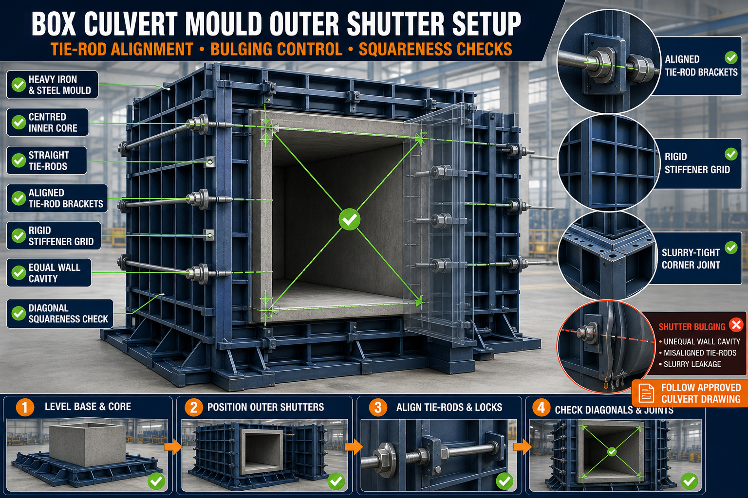
Box Culvert Mould Outer Shutter Setup: Tie-Rod Alignment, Bulging Control and Squareness Checks
Box Culvert Mould Outer Shutter Setup Guide
A precast box culvert mould normally consists of an inner core and heavy outer shutters that form the external faces of the concrete unit. These shutters must remain accurately aligned while carrying fresh concrete pressure and vibration forces.
If a shutter moves outward, bends between stiffeners or closes out of square, the finished culvert may have unequal wall thickness, dimensional variation or installation problems. Incorrect tie-rod positioning can also concentrate load on the shutter and damage its brackets.
This guide explains box culvert mould outer shutter setup, including tie-rod alignment, bulging control, flange sealing and squareness checks.
What Is a Box Culvert Outer Shutter?
The outer shutter is the heavy iron or structural-steel mould section that forms the outside faces of a precast box culvert.
A typical outer-shutter assembly may include:
• Heavy iron shutter plates • Structural stiffeners • Vertical and horizontal ribs • C-channels or other structural sections • Tie rods • Tie-rod brackets • Spacers or sleeves • Hinges • Flange joints • Alignment pins • Mechanical locks • Wedges or clamps • Slurry seals • Mechanical stops • Base-frame connections
The exact arrangement should follow the approved box culvert mould drawing.
Why Outer-Shutter Alignment Is Important
Correct outer-shutter setup helps maintain:
• Overall culvert width • Overall culvert height • Wall thickness • Slab thickness • Corner squareness • Straight outer faces • Joint alignment • Opening dimensions • Slurry control • Consistent production quality
A small setup error can affect several dimensions of the finished culvert.
Common Outer-Shutter Problems
Typical setup and operating problems include:
• Shutter leaning outward • Unequal distance from the inner core • Tie rods installed at an angle • Loose tie-rod nuts • Bent shutter plates • Gaps at flange joints • Misaligned corners • Unequal diagonal measurements • Bulging between stiffeners • Damaged seals • Concrete fins • Locks becoming difficult to engage
These problems should be corrected before reinforcement and concrete placement.
Safety Before Shutter Setup
Box culvert shutters are large and heavy. They can move unexpectedly during positioning or maintenance.
Before beginning:
1. Stop nearby mould operations. 2. Clear the work area. 3. Inspect the lifting equipment. 4. Confirm the shutter weight and handling method. 5. Use only approved lifting points. 6. Support every shutter mechanically. 7. Keep personnel away from pinch points. 8. Isolate hydraulic systems where fitted. 9. Apply the plant’s lockout procedure when required. 10. Wear suitable personal protective equipment.
Never stand beneath a suspended shutter or between an unsecured shutter and the inner core.
Prepare the Mould Foundation
Outer-shutter accuracy begins with a level and stable base.
Inspect:
• Foundation level • Base-frame contact • Support-point condition • Anchor bolts • Levelling plates • Concrete buildup beneath the mould • Frame straightness • Welded joints • Modular connections • Signs of settlement
Do not use random scrap steel, broken concrete or wooden pieces as permanent packing beneath a heavy mould.
Clean All Contact Surfaces
Before closing the shutters, clean:
• Base locating surfaces • Corner joints • Flanges • Alignment-pin holes • Tie-rod brackets • Locking points • Mechanical stops • Inner-core reference surfaces • Gasket grooves • Shutter edges
Hardened slurry can prevent complete closure and affect squareness.
Inspect the Outer Shutters
Check each shutter before assembly.
Look for:
• Plate bowing • Bent stiffeners • Cracked welds • Damaged edges • Misaligned flanges • Worn hinges • Damaged locking brackets • Enlarged tie-rod holes • Corrosion • Previous repairs • Loose structural members • Distorted lifting points
A damaged shutter should be repaired and inspected before production.
Establish a Fixed Datum
Use one fixed mould reference for all outer-shutter measurements.
The datum may be:
• One base-frame corner • A marked mould centreline • A fixed end frame • A machined locating surface • An approved survey reference
Measure each shutter and tie-rod location from this datum to avoid accumulated errors.
Position the Inner Core First
The outer shutters are normally aligned in relation to the mould base and inner core. Confirm that the inner core is:
• Correctly positioned • Centred according to the approved drawing • Properly supported • Dimensionally stable • Square with the base • Fully expanded or locked where applicable • Clean at all contact locations • Protected against unwanted movement
Outer-shutter adjustment cannot correct a misaligned inner core.
Initial Outer-Shutter Positioning
A controlled positioning process may include:
1. Clean the mould base. 2. Establish the fixed datum. 3. Position the inner core. 4. Move each outer shutter slowly. 5. Engage the bottom locating points. 6. Install alignment pins. 7. Engage locks lightly. 8. Install tie rods loosely. 9. Check clearances and wall spaces. 10. Complete alignment before final tightening.
Do not pull a badly misaligned shutter into position only by tightening the tie rods.
What Is the Purpose of Tie Rods?
Tie rods connect or restrain opposite shutter sections so they can resist outward pressure during concrete casting.
Tie rods help:
• Maintain the shutter position • Control outward movement • Reduce bulging • Maintain wall thickness • Support joint closure • Transfer load between structural brackets • Keep opposite shutters aligned
Tie rods must be used according to the mould design.
Tie-Rod Alignment
A tie rod should pass through its intended brackets and remain aligned with the designed load path.
Check:
• Rod straightness • Bracket position • Hole alignment • Spacer or sleeve position • Washer contact • Nut engagement • Clearance from reinforcement • Contact with the mould structure • Orientation relative to opposite shutters
An angled or bent tie rod may create uneven force and damage the shutter bracket.
Inspect Tie Rods Before Use
Check every tie rod for:
• Bending • Damaged threads • Corrosion • Cracks • Previous welding • Worn nuts • Damaged washers • Incorrect length • Deformed end connections • Concrete contamination
Do not use improvised rods or unapproved replacement fasteners.
Tie-Rod Tightening Sequence
Tie rods should be tightened gradually and in a balanced pattern.
A suitable sequence is:
1. Install all rods loosely. 2. Confirm shutter seating. 3. Align the corner flanges. 4. Engage all locks lightly. 5. Tighten opposite rods gradually. 6. Work from selected reference locations outward. 7. Maintain balanced pressure. 8. Recheck wall spaces. 9. Check shutter straightness. 10. Complete final tightening. 11. Recheck diagonal measurements.
The approved sequence may vary according to the mould design.
Avoid Over-Tightening Tie Rods
Excessive tightening can:
• Pull shutters inward • Change wall thickness • Distort brackets • Bend shutter plates • Damage seals • Misalign corners • Overload threads • Make demoulding difficult
Tie rods should restrain the shutters without forcing the mould out of shape.
What Is Outer-Shutter Bulging?
Bulging is the outward deflection of a shutter plate or frame under fresh concrete pressure.
Bulging may occur:
• Between stiffeners • Near tie-rod brackets • Around large unsupported areas • At modular joints • Near damaged welds • At the middle of long shutters • Around previous repair locations
Bulging can create an oversized external profile and unequal wall thickness.
Common Causes of Bulging
Possible causes include:
• Insufficient structural stiffening • Missing tie rods • Loose tie-rod nuts • Damaged brackets • Bent shutter plates • Cracked welds • Excessive unsupported plate area • Uneven concrete placement • Uncontrolled filling rate • Excessive vibration • Incorrect lock engagement • Worn modular joints
The cause should be identified before attempting adjustment.
Inspect the Stiffener Grid
The stiffener grid supports the shutter plate and distributes concrete pressure.
Inspect:
• Vertical stiffeners • Horizontal stiffeners • Cross members • Edge frames • Diagonal bracing • Welded connections • Tie-rod load points • Local plate support • Corrosion • Impact damage
A stiffener that has separated from the shutter plate cannot provide the intended support.
Check Shutter Straightness
Use a suitable inspection method to check the shutter before casting.
Possible tools include:
• Straightedge • String line • Laser reference • Survey equipment • Approved checking template
Check:
• Along the shutter length • Along the shutter height • Across modular joints • Between tie-rod locations • Around repaired areas • Along flange-contact surfaces
Compare the result with the approved mould tolerance.
Wall-Thickness Checks
Wall thickness is controlled by the distance between the outer shutter and inner core.
Check the spacing:
• At all four corners • Along the top • Along the bottom • At intermediate points • Near tie rods • At modular joints • Around openings or inserts • After final tightening
Use an approved gauge or measurement method.
Do Not Measure Cumulatively
Use the same fixed datum and inner-core reference for every inspection location. Measuring each point only from the previous one may hide accumulated setup errors.
What Is a Squareness Check?
Squareness confirms that the mould corners and opposite faces are positioned correctly.
A mould may appear aligned from one side but still be twisted or out of square.
Squareness affects:
• Culvert opening • External dimensions • Joint fit • Installation alignment • Stacking • Corner geometry • Connection between adjacent units
Diagonal Measurement
Comparing approved diagonal references is a common method of checking squareness.
A controlled procedure includes:
1. Identify matching reference points. 2. Clean the points. 3. Measure both diagonals. 4. Use the same measuring method. 5. Compare the results. 6. Adjust shutters gradually. 7. Recheck after locking. 8. Record the final measurements.
The acceptable difference should follow the approved mould drawing and quality plan.
Check Squareness at Both Ends
A long box culvert mould can be square at one end and twisted at the other.
Check:
• Front-end diagonals • Rear-end diagonals • Intermediate section where required • Inner-core position • Top-frame alignment • Bottom-frame alignment • Modular-joint position
Do not rely on only one diagonal check.
Check Corner Flange Alignment
At each corner, inspect:
• Alignment-pin engagement • Flange contact • Internal step • External step • Joint gap • Seal condition • Lock position • Welded corner support
Corner joints should close evenly without being forced.
Slurry Control at Shutter Joints
Cement slurry can escape through gaps in flanges, corners and tie-rod penetrations.
Common leakage points include:
• Vertical corner joints • Bottom shutter joint • Modular flanges • Tie-rod holes • Damaged gasket sections • Locking points • Inner-core joints • Previous repair areas
Slurry leakage may create concrete fins, honeycombing and difficult demoulding.
Inspect Gaskets and Seals
Check sealing material for:
• Cuts • Cracks • Hardening • Flattening • Missing sections • Incorrect positioning • Concrete contamination • Oil damage • Uneven compression
Use compatible sealing material according to the mould design.
Locking-System Inspection
Outer-shutter locks help maintain joint closure during casting.
Inspect:
• Wedge locks • Clamps • Pins • Bolts • Locking brackets • Contact pads • Threads • Retainers • Welded supports • Handle movement
Damaged locks should be repaired before the mould is loaded.
Balanced Lock Adjustment
Engage locks gradually around the mould.
Locks should:
• Maintain flange contact • Compress seals evenly • Remain easy to release • Avoid bending shutter edges • Work together with tie rods • Stay secure during vibration
Do not use locks to compensate for structural misalignment.
Reinforcement and Insert Clearance
After outer-shutter alignment, check that reinforcement and inserts do not interfere with the mould.
Inspect:
• Reinforcement cover • Cage position • Spacer stability • Lifting anchors • Connection inserts • Tie-rod clearance • Inner-core clearance • Corner reinforcement • Embedded components
Reinforcement should not push the shutter or inner core out of position.
Apply Mould-Release Agent
Apply a suitable release agent uniformly to clean iron casting surfaces.
The release agent should be:
• Compatible with precast concrete • Applied in a thin layer • Prevented from pooling • Kept away from required bond areas • Suitable for seals and inserts • Used according to the manufacturer’s instructions
Excessive release agent may cause stains and surface defects.
Pre-Casting Setup Checklist
Before pouring concrete, confirm:
• Mould foundation is level • Inner core is aligned and locked • Outer shutters are correctly seated • Tie rods are straight and engaged • Tie-rod brackets are undamaged • Locks are secure • Stiffeners are intact • Wall spaces are checked • Diagonals are verified • Corner flanges are closed • Seals are correctly compressed • Reinforcement is positioned • Casting surfaces are clean • Release agent is applied
Record the inspection according to the plant’s quality procedure.
Concrete Placement for Bulging Control
Concrete should be placed in a balanced and planned sequence.
During casting:
• Distribute concrete evenly • Avoid filling only one side • Control the filling rate • Monitor tie rods and locks • Observe shutter reference points • Avoid excessive concrete impact • Stop if abnormal movement appears • Check for slurry leakage
The approved placement process should reflect the mould size and concrete mix.
Controlled Vibration
Vibration should compact concrete without overloading the shutter system.
During vibration:
• Use the approved vibration equipment • Avoid excessive vibration • Maintain balanced vibrator placement • Monitor locking points • Check tie rods • Watch for flange leakage • Listen for abnormal noise • Stop if the shutter moves
Do not allow a poker vibrator to strike the iron shutter, tie rods, reinforcement or inserts unnecessarily.
Monitoring During Casting
Use safe, visible reference points to observe:
• Shutter movement • Tie-rod position • Lock engagement • Corner gaps • Slurry leakage • Frame vibration • Inner-core stability • Reinforcement movement
Do not enter unsafe areas or adjust loaded components without an approved procedure.
Post-Casting Inspection
After demoulding, inspect the mould for:
• Loose tie rods • Bent brackets • Changed shutter straightness • Cracked welds • Damaged seals • Concrete buildup • Lock wear • Modular-joint movement • Stiffener damage • Changed diagonal measurements
Repeated movement at the same location may indicate a structural problem.
Finished Culvert Quality Checks
Inspect the precast box culvert for:
• Overall dimensions • Wall and slab thickness • Opening dimensions • Corner squareness • Surface straightness • Joint profile • Concrete fins • Honeycombing • Cracks • Insert position • Edge condition
Final acceptance should follow the approved product drawing and project quality plan.
Common Problems and Corrective Actions
Tie Rod Does Not Align With Its Bracket
Check shutter position, bracket deformation, inner-core alignment and base-frame squareness. Do not force the rod through.
Shutter Bulges Between Stiffeners
Inspect the plate, stiffener welds, tie-rod arrangement, concrete-placement sequence and vibration.
Diagonal Measurements Are Unequal
Loosen selected locks and tie rods, correct the shutter position from the fixed datum and recheck both ends.
Wall Thickness Is Unequal
Check the inner core, outer-shutter position, tie-rod tightening and reinforcement interference.
Slurry Leaks From a Corner
Inspect flange cleanliness, alignment pins, gasket condition and lock pressure.
Locks Become Difficult to Release
Possible causes include excessive tightening, slurry entry, mould distortion or loading beyond the approved setup.
Concrete Fin Appears at a Joint
Check joint gaps, damaged seals, concrete buildup and flange straightness.
Preventive Maintenance Checklist
After Every Casting Cycle
• Clean flanges and tie rods • Remove slurry from locks • Inspect visible shutter movement • Check sealing surfaces • Clean locating points • Inspect concrete leakage areas
Scheduled Checks
• Check shutter straightness • Inspect tie rods and threads • Examine stiffeners and welds • Verify diagonal references • Inspect alignment pins • Check locks and brackets • Replace damaged seals • Check base-frame level • Record recurring defects • Verify mould dimensions
When Should Production Be Stopped?
Stop using the box culvert mould if you find:
• Cracked structural welds • Severely bent shutters • Missing or damaged tie rods • Failed tie-rod brackets • Major bulging • Unstable mould supports • Locks that cannot engage • Incorrect wall spaces • Unacceptable diagonal differences • Major slurry leakage • Unsafe shutter movement
Production should resume only after repair and dimensional verification.
Conclusion
Correct box culvert mould outer shutter setup depends on a level base, aligned inner core, straight tie rods, balanced locking and accurate squareness checks.
Tie rods should restrain the heavy iron shutters without pulling them out of position. The stiffener grid, flange seals and locks must work together to control bulging and slurry leakage during concrete placement and vibration.
Paras Steel Industries manufactures heavy-duty iron and structural-steel box culvert moulds according to customer requirements and approved drawings. A planned setup and inspection process can support accurate dimensions, cleaner concrete surfaces and consistent precast production.