
Precast Mould Guide
Box Culvert Mould Inner-to-Outer Shutter Spacing: Wall Thickness and Core-Shift Inspection
The spacing between a box culvert mould’s inner core and outer shutters determines the concrete wall and slab thickness. A shifted, tilted or bowed core can produce unequal walls, incorrect reinforcement cover and difficult demoulding. This guide explains spacing measurements, core-shift diagnosis and pre-pour alignment checks.
By Paras Steel Industries ·
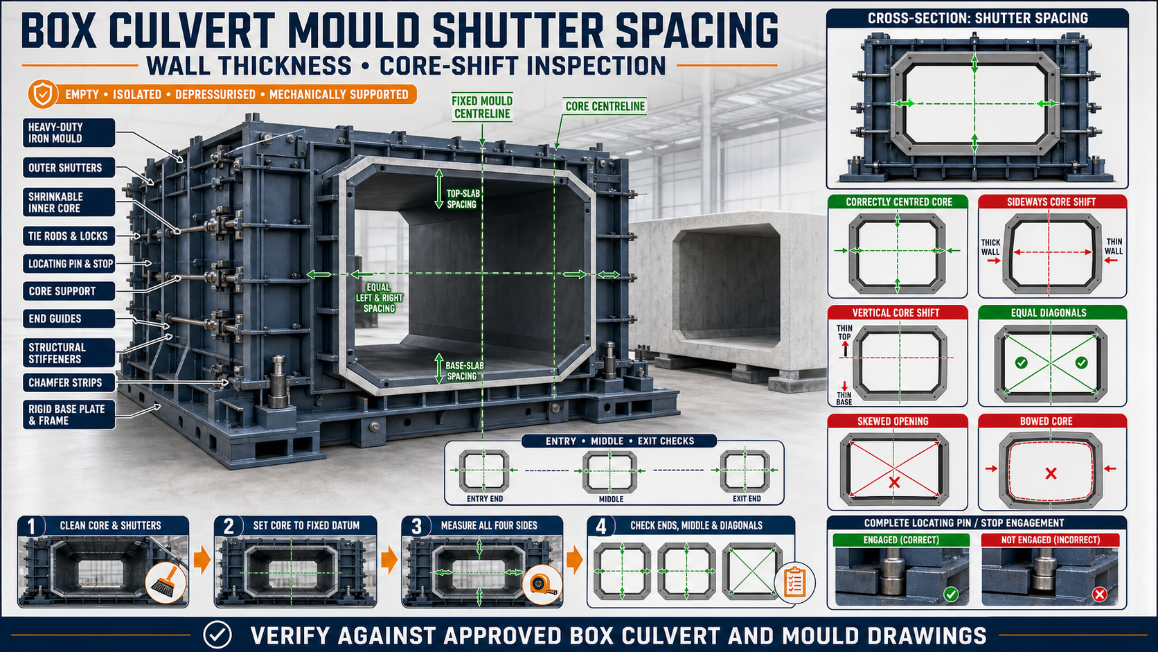
Box Culvert Mould Inner-to-Outer Shutter Spacing: Wall Thickness and Core-Shift Inspection
Box Culvert Mould Inner-to-Outer Shutter Spacing: Wall Thickness and Core-Shift Inspection
A precast box culvert is formed inside the cavity created between the mould’s outer shutters and inner core. The position of these components controls the culvert’s wall thickness, top-slab thickness, base thickness and internal opening.
If the inner core shifts sideways, rises, settles or becomes twisted, the finished culvert may have unequal sections. One wall may become thicker while the opposite wall becomes thinner.
Accurate inner-to-outer shutter spacing is therefore essential for dimensional consistency, reinforcement cover, joint matching and reliable demoulding.
What Is Inner-to-Outer Shutter Spacing?
Inner-to-outer shutter spacing is the distance between the inner-core forming surface and the corresponding outer-shutter forming surface.
This spacing creates the concrete sections of the culvert, including:
• Left wall • Right wall • Top slab • Base slab • Corner transitions • Haunches where specified • End-joint areas
Every spacing requirement should come from the approved box culvert drawing.
Main Components of a Box Culvert Mould
A heavy-duty iron box culvert mould may include:
• Outer side shutters • Outer top shutter where applicable • Mould base • Shrinkable inner core • Inner-core forming plates • Structural stiffeners • Tie rods • Wedge locks • End shutters • Chamfer strips • Joint formers • Core-support system • Mechanical or hydraulic operating components • Locating pins and stops
The alignment of every component affects the final cavity.
What Is Core Shift?
Core shift occurs when the inner core moves away from its intended position.
The movement may be:
• Sideways • Upward • Downward • Longitudinal • Rotational • Local due to bowing • Different at each end • Progressive during concrete casting
A core can be centred before casting and still move under concrete pressure if it is not secured correctly.
Why Wall-Thickness Accuracy Is Important
Correct wall and slab thickness helps maintain:
• Approved culvert dimensions • Reinforcement cover • Internal waterway opening • External installation dimensions • Joint compatibility • Concrete quantity control • Product weight consistency • Demoulding clearance • Reliable production quality
The structural acceptance of a culvert must follow the approved design and quality requirements.
Symptoms of Incorrect Shutter Spacing
Possible warning signs include:
• One wall thicker than the opposite wall • Top slab thickness variation • Uneven base thickness • Internal opening shifted sideways • Different diagonal measurements • Joint profiles not matching • Reinforcement cover variation • Concrete rubbing or binding during demoulding • Repeated corner damage • Culvert units not aligning during trial fit
Recurring defects should be mapped back to the mould position.
Common Causes of Core Shift
The inner core may move because of:
• Worn locating pins • Loose mechanical stops • Uneven support brackets • Core-support settlement • Hydraulic cylinder mismatch • Worn pivot pins or bushes • Loose shrinkable-core locks • Bent forming plates • Damaged stiffeners • Unequal concrete placement • Excessive vibration • Reinforcement interference • End-shutter misalignment • Slurry buildup • Foundation movement • Incorrect repair work
The complete system should be inspected before changing one adjustment point.
Types of Box Culvert Inner Cores
Fixed Inner Core
A fixed core may suit moulds where the product and opening arrangement allow direct removal.
Removable Inner Core
The complete core is withdrawn after adequate concrete release.
Shrinkable Inner Core
Sections move inward to create clearance before removal.
Collapsible Inner Core
Multiple panels fold or collapse through a controlled mechanism.
Hydraulic Inner Core
Hydraulic cylinders operate some or all core sections.
The correct inspection process depends on the actual mould design.
Preparing the Mould for Spacing Inspection
Before measurement:
• Empty and clean the mould • Remove hardened concrete • Isolate electrical equipment • Release hydraulic pressure • Mechanically support movable sections • Lock the core in casting position • Secure outer shutters • Clean locating stops • Review approved drawings • Identify fixed mould datums • Prepare suitable measuring equipment
Never work inside or beneath a core supported only by hydraulic pressure.
Establishing a Fixed Mould Datum
Measurements should be related to stable, verified references.
Possible datums include:
• Mould-base centreline • Base-frame edge • Machined locating surface • Fixed end-frame centreline • Survey benchmark • Verified mould-bed elevation • Approved alignment stops
Do not use dirty, damaged or unchecked movable shutters as the only reference.
Marking the Core Centreline
A visible centreline can be transferred across:
• Mould base • End frames • Inner core • End shutters • Core supports • Inspection jigs
The core centreline should match the fixed mould centreline when the core is in casting position.
Creating a Measurement Plan
A large box culvert mould should be measured at several stations.
Typical inspection locations include:
• Entry end • Exit end • Middle • Intermediate support points • Upper corners • Lower corners • Side-wall midpoints • Top-slab cavity • Base cavity • Joint-former locations
The exact measurement grid should suit the mould and product drawing.
Checking Left and Right Wall Spacing
Measure corresponding points on both sides.
A general procedure includes:
1. Clean the Forming Surfaces
Remove all deposits that can affect measurements.
2. Set the Core in Casting Position
Engage approved locks and mechanical stops.
3. Close the Outer Shutters
Use the approved balanced locking sequence.
4. Verify the Mould Centreline
Confirm the datum before comparison.
5. Measure the Left Cavity
Check at several heights and stations.
6. Measure the Right Cavity
Use matching positions.
7. Compare the Readings
Identify side shift, bowing or shutter misalignment.
8. Record the Results
Keep readings for future comparison.
No generic spacing tolerance should be assumed.
Checking Top-Slab Spacing
The top-slab cavity is the space between the upper inner-core surface and outer top shutter or corresponding mould plate.
Check:
• Both ends • Centre • Intermediate positions • Areas near hydraulic supports • Corner transitions • Joint-former areas
Unequal top spacing may indicate core tilt, vertical shift or outer-shutter distortion.
Checking Base-Slab Spacing
Base thickness is controlled by the clearance between the lower core surface and mould base.
Inspect:
• All four corners • Middle • Cross-support locations • Core-support points • Shrinkable-joint areas • End-guide locations
A low core reduces the cavity below it, while a high core increases it.
Checking Culvert Diagonals
Diagonal measurements can reveal core skew or twist.
Compare:
• Internal opening diagonals • Core-frame diagonals • Outer-mould diagonals • End-frame relationships • Corresponding readings at both ends
Unequal diagonals may indicate a parallelogram-shaped or twisted opening.
Checking Inner-Core Straightness
A core may have correct end positions but bow through the middle.
Possible inspection methods include:
• Laser alignment • Tensioned reference line • Verified straightedge • Survey equipment • Approved inspection fixture • Dial-indicator arrangement
Inspect both horizontal and vertical forming surfaces.
Checking Outer-Shutter Straightness
Unequal spacing is not always caused by the inner core.
Inspect the outer shutters for:
• Bowing • Local plate bulging • Bent stiffeners • Loose tie rods • Damaged locks • Cracked welds • Concrete buildup • Uneven foundation support • Repair distortion
Both sides of the cavity must be evaluated.
Core Shift vs Outer-Shutter Movement
Core shift may be suspected when:
• Internal opening moves relative to the mould centreline • Both opposing cavity measurements change together • Core-support locations have moved • End-guide positions differ • Shrinkable-core locks contain play
Outer-shutter movement may be suspected when:
• Core centreline remains correct • Only one external cavity face changes • Tie rods or locks are loose • Outer shutter is visibly bowed • Base-frame mounting has shifted
Both conditions may occur simultaneously.
Inspecting Core Supports
Core supports establish the vertical and horizontal position of the inner core.
Inspect:
• Support height • Bearing contact • Adjustment screws • Steel shims • Mounting bolts • Welds • Brackets • Mechanical stops • Signs of movement • Local base-frame distortion
Improvised packing should not be used for permanent alignment.
Inspecting Locating Pins and Guide Blocks
Locating components help return the core to the same casting position.
Check for:
• Bent pins • Worn bushes • Enlarged holes • Damaged guide faces • Slurry buildup • Loose mounting • Cracked welds • Incomplete engagement • Uneven contact • Corrosion
Worn locating points can create different spacing in every production cycle.
Inspecting the Shrinkable-Core Mechanism
A shrinkable core should lock rigidly in its casting position and retract smoothly for demoulding.
Inspect:
• Folding plates • Sliding surfaces • Pivot pins • Bushes • Linkages • Locking wedges • Hydraulic cylinders • Mechanical stops • Forming-surface joints • Internal supports
Movement or play in the mechanism can change wall thickness.
Checking Tie Rods and Locks
Outer shutters must resist fresh concrete pressure.
Inspect:
• Tie-rod straightness • Thread condition • Nuts and washers • Lock brackets • Wedge surfaces • Pin holes • Welds • Engagement depth • Alignment • Signs of stretching or impact
Unequal tightening can pull a shutter out of alignment.
End-Shutter and Core Alignment
End shutters connect the inner and outer mould geometry.
Check:
• Core centreline at the end • Cavity spacing around the complete profile • Joint-former position • End-shutter squareness • Locking sequence • Chamfer transitions • Slurry-sealing surfaces
A misaligned end shutter may pull the core or outer shutters away from their correct positions.
Reinforcement Clearance
The reinforcement cage should fit correctly inside the cavity without pushing the mould components.
Check:
• Cage dimensions • Concrete-cover spacers • Bar position • Corner reinforcement • Joint-area reinforcement • Lifting inserts where approved • Clearance from core joints • Tie-wire position • Stability during shutter closing
Do not force the mould shut against incorrectly placed reinforcement.
Concrete-Cover Control
The reinforcement position should provide the cover specified in the approved structural drawing.
Cover may change due to:
• Core shift • Outer-shutter movement • Unstable spacers • Reinforcement displacement • Concrete impact • Vibration • Incorrect cage fabrication
Mould spacing and reinforcement position should be inspected together.
Chamfer-Strip Alignment
Chamfer strips form controlled bevelled corners.
Check that they:
• Follow the correct profile • Remain straight • Meet end shutters cleanly • Do not change cavity spacing • Are securely attached • Have no slurry buildup • Allow core retraction • Match the approved drawing
A displaced strip can create a false spacing reading at the corner.
Applying Mould Release Agent
After the mould is cleaned and aligned, apply a suitable release agent.
The application should be:
• Thin • Uniform • Complete across forming surfaces • Present around core joints • Applied to chamfer strips • Free from excessive pooling • Kept away from reinforcement
Release agent cannot compensate for misalignment or damaged plates.
Pre-Pour Spacing Inspection Checklist
Before casting, confirm:
• Mould is clean • Core is fully expanded into casting position • Core centreline matches the mould datum • Left and right spacing is verified • Top and base spacing is checked • Internal diagonals are correct • Core supports are secure • Locating pins are engaged • Outer shutters are straight • Tie rods and locks are secured • End shutters are aligned • Joint formers are positioned correctly • Reinforcement has adequate clearance • Release agent is uniformly applied • No tools remain inside the mould
Record critical measurements according to the quality procedure.
Concrete Placement and Core Shift
Uneven concrete placement can create lateral pressure against the inner core.
To reduce movement:
• Place concrete progressively • Maintain similar levels on opposite sides • Avoid filling one wall completely first • Prevent direct impact on the core • Follow the approved pour sequence • Monitor tie rods and locks • Keep reinforcement stable • Observe the core reference marks
The mould should not be left unattended during critical filling stages.
Concrete Pressure on Shutters
Fresh concrete applies pressure to both the inner core and outer shutters.
The pressure is influenced by:
• Concrete workability • Placement rate • Pour height • Vibration • Temperature • Mould geometry • Production method
The mould should be operated only within its approved design and production procedure.
Effect of Vibration
Vibration can loosen worn or incorrectly secured components.
Before vibration:
• Check core locks • Check outer-shutter locks • Inspect tie rods • Confirm mechanical stops • Verify support contact • Remove loose tools
During vibration, observe for:
• Core movement • Shutter bulging • Changing joint gaps • Slurry leakage • Lock movement • Unusual metallic noise • Altered centreline marks
Stop the process safely if significant movement occurs.
Checking for Core Movement After Casting
Where the production procedure permits, inspect accessible reference points after concrete placement.
Check:
• Core centre marks • Lock position • Tie-rod condition • End-guide contact • Shutter gaps • Visible movement marks
Do not enter hazardous areas or measure through fresh concrete.
Preparing for Demoulding
Before shrinking the inner core:
• Confirm adequate concrete strength • Support the box culvert • Isolate powered equipment • Release hydraulic pressure as required • Secure moving components • Clean exposed locks • Identify the approved release sequence • Keep personnel clear of pinch points • Prepare suitable handling equipment
Concrete strength and timing should follow the production procedure.
Correct Core-Release Sequence
The exact process depends on the core design. A general sequence may include:
1. Support the Culvert
Prevent unexpected movement.
2. Release Secondary Locks
Open components that do not carry the main core position.
3. Release Core Locks Progressively
Avoid sudden movement.
4. Activate the Shrinking Mechanism
Retract the core sections evenly.
5. Verify Clearance on All Sides
Confirm that one section is not still contacting the concrete.
6. Withdraw or Lower the Core Safely
Follow the designed movement path.
7. Open Outer Shutters
Maintain support for the concrete unit.
8. Inspect the Finished Culvert
Check walls, slabs, opening and corners.
Never force a core that has not fully retracted.
Post-Demoulding Wall-Thickness Inspection
Measure the finished culvert at corresponding locations.
Check:
• Left wall thickness • Right wall thickness • Top slab • Base slab • Corners • Ends • Middle • Joint regions
Compare product readings with the pre-pour mould measurements.
Inspecting the Internal Opening
Check:
• Width • Height • Centreline • Diagonals • Straightness • Corner profile • Surface finish • Joint continuity
A shifted internal opening often indicates inner-core movement.
Troubleshooting Common Problems
Problem: One Wall Is Thick and the Opposite Wall Is Thin
Possible causes:
• Core shifted sideways • Locating pin is worn • Support bracket moved • Reinforcement pushed the core • Concrete was placed unevenly • Outer shutter moved
Problem: Top Slab Is Thick on One Side
Possible causes:
• Core is tilted • Top outer shutter is misaligned • Support heights differ • Core is twisted • End guides are uneven
Problem: Base Slab Thickness Changes Along the Culvert
Possible causes:
• Core support settlement • Mould base is not level • Core is bowed • End supports differ • Base plate is distorted
Problem: Internal Opening Is Out of Square
Possible causes:
• Core diagonals are unequal • Shrinkable sections are not fully locked • End frame is misaligned • Core is twisted • Outer mould is distorted
Problem: Core Moves During Vibration
Possible causes:
• Core locks are worn • Mechanical stops are loose • Support contact is incomplete • Hydraulic system is not holding the approved position • Vibration is uncontrolled
Problem: Culvert Is Difficult to Demould
Possible causes:
• Core did not fully retract • Concrete fins locked a core joint • Core taper or forming surface is damaged • Release agent coverage is poor • Product is distorted • Demoulding strength is incorrect
Problem: Reinforcement Cover Is Uneven
Possible causes:
• Core shift • Shutter movement • Unstable spacers • Cage fabrication error • Concrete placement moved the reinforcement
Correcting Core Alignment
A controlled correction plan may involve:
• Cleaning locating surfaces • Replacing worn pins and bushes • Adjusting approved stops • Repairing support brackets • Correcting core straightness • Synchronizing hydraulic movement • Realigning end guides • Inspecting the mould foundation • Rechecking all spacing points
Do not use random shims or excessive hydraulic pressure to force the core into position.
Mould Maintenance Checklist
After every production cycle:
• Clean inner and outer forming surfaces • Remove slurry from core joints • Inspect core supports • Check locating pins • Inspect locks and wedges • Check pivot pins and bushes • Inspect hydraulic components where fitted • Check tie rods • Inspect outer-shutter straightness • Examine welds and stiffeners • Clean end guides • Confirm shrinkable-core movement • Apply corrosion protection during storage • Record recurring thickness defects
Regular records help detect progressive movement before it causes major rejection.
Benefits of Correct Shutter Spacing
Accurate inner-to-outer spacing provides:
• Consistent wall thickness • Correct top and base slabs • Centred internal opening • Better reinforcement-cover control • Cleaner corner profiles • Improved joint compatibility • Easier demoulding • Reduced concrete variation • Lower rejection and repair • More repeatable culvert production
Conclusion
The spacing between a box culvert mould’s inner core and outer shutters determines the wall, top-slab and base-slab dimensions of the finished concrete unit.
A reliable inspection should compare the core and shutters with fixed mould datums at both ends, the middle and critical support locations. Core supports, locating pins, shrinkable mechanisms, tie rods, end shutters and reinforcement clearance should all be checked before casting.
A properly aligned heavy-duty iron box culvert mould helps manufacturers produce dimensionally consistent culverts with equal sections, centred openings and reliable demoulding performance.