
Precast Mould Guide
Box Culvert Mould Chamfer Strip Alignment: Corner Finish, Leakage and Edge-Damage Prevention
Chamfer strips form the bevelled corners of a precast box culvert and help reduce sharp, fragile concrete edges. Loose, damaged or misaligned strips can cause slurry leakage, uneven chamfers and difficult demoulding. This guide explains chamfer-strip positioning, fastening, sealing and maintenance for heavy-duty iron box culvert moulds.
By Paras Steel Industries ·
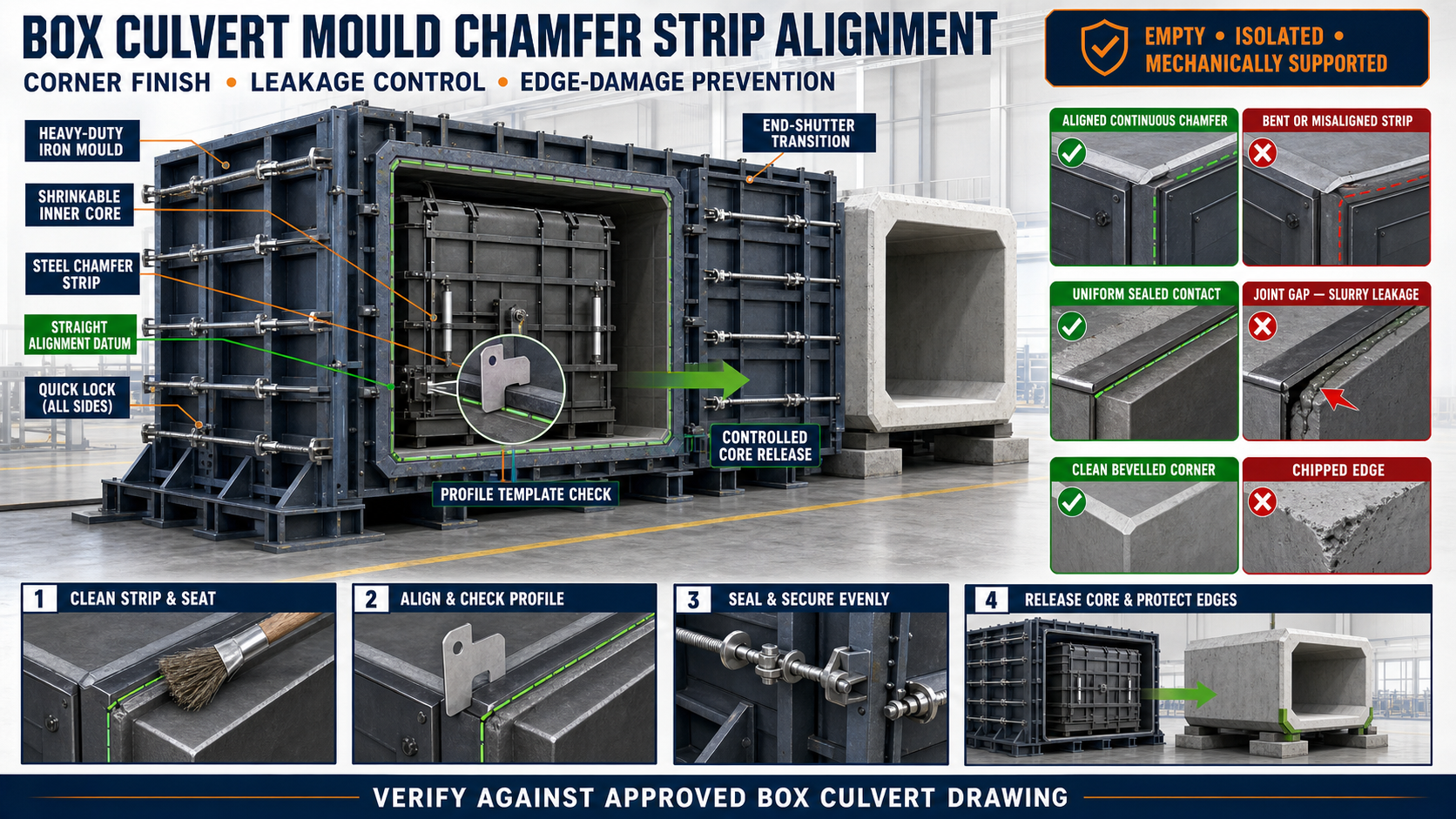
Box Culvert Mould Chamfer Strip Alignment: Corner Finish, Leakage and Edge-Damage Prevention
Box Culvert Mould Chamfer Strip Alignment: Corner Finish, Leakage and Edge-Damage Prevention
A precast box culvert contains several internal and external corners that must remain dimensionally accurate and structurally sound. Completely sharp concrete corners are vulnerable to chipping during demoulding, lifting, transportation and installation.
Chamfer strips create controlled bevelled edges at specified culvert corners. They also improve concrete flow and provide a more consistent finished appearance.
However, a loose, damaged or incorrectly positioned chamfer strip can cause an uneven profile, slurry leakage, concrete fins and corner damage. Accurate strip alignment is therefore an important part of box culvert mould preparation.
What Is a Chamfer Strip?
A chamfer strip is a shaped iron or steel insert installed along a mould corner to create a bevelled edge on the finished concrete product.
In a heavy-duty box culvert mould, chamfer strips may be installed at:
• Inner-core corners • Outer-shutter corners • Culvert opening edges • End-shutter intersections • Base corners • Joint-forming areas • Project-specific edge locations
The required position and profile should follow the approved box culvert drawing.
Functions of a Chamfer Strip
A correctly installed strip helps:
• Remove fragile sharp concrete edges • Produce a uniform corner profile • Improve visual finish • Reduce edge chipping • Support smooth concrete flow • Simplify demoulding • Improve repeatability • Control corner dimensions • Reduce repair work • Protect edges during handling
A chamfer does not compensate for incorrect mould dimensions or poor concrete compaction.
Chamfer Strip Construction
Industrial box culvert moulds commonly use rigid iron or steel chamfer-forming components.
A strip system may include:
• Shaped steel bar • Formed steel plate • Welded profile strip • Removable bolted strip • Locating stops • Clamping points • Sealing surfaces • Corner transition pieces • Tapered end sections
The strip must remain sufficiently rigid to resist movement during concrete filling and vibration.
Fixed vs Removable Chamfer Strips
Fixed Chamfer Strips
Fixed strips are welded or permanently attached to the mould.
Advantages may include:
• Repeatable location • Fewer loose components • Faster mould preparation • Reduced risk of incorrect installation
They require careful repair if they become worn or distorted.
Removable Chamfer Strips
Removable strips may be bolted, pinned or clamped.
Advantages may include:
• Easier replacement • Profile-change flexibility • Improved access for cleaning • Simplified repair
Their position and locking should be checked before every casting cycle.
Why Chamfer-Strip Alignment Is Important
Incorrect alignment can create:
• Uneven chamfer width • Broken corner transitions • Concrete fins • Slurry leakage • Local honeycombing • Difficulty during demoulding • Culvert edge damage • Inconsistent appearance • Dimensional variation • Increased grinding and patching
A strip that is correct at one end may still be displaced at the middle or opposite end.
Common Causes of Misalignment
Chamfer-strip alignment can change because of:
• Concrete buildup behind the strip • Loose fasteners • Worn locating points • Bent steel profile • Cracked welds • Impact during cleaning • Incorrect installation • Uneven clamping • Outer-shutter distortion • Inner-core movement • End-shutter misalignment • Excessive vibration • Thermal distortion after repair welding
The mould corner and supporting structure should both be inspected.
Preparing the Mould for Inspection
Before checking chamfer strips:
• Empty and clean the mould • Remove concrete residue • Isolate hydraulic equipment • Release stored pressure safely • Mechanically support movable shutters • Secure the shrinkable inner core • Open access panels where required • Identify the approved inspection datum • Review the culvert drawing • Keep suitable measuring tools ready
Never inspect internal corners while the core or shutters can move unexpectedly.
Identify Required Chamfer Locations
Not every corner necessarily uses the same profile.
Mark or record:
• Internal chamfer locations • External chamfer locations • Different strip profiles • Casting direction • Left and right components • End-transition details • Joint-forming areas • Removable-strip identification
This reduces the risk of installing a strip in the wrong location.
Establishing an Alignment Datum
The strip should be checked against a verified mould reference.
Suitable reference points may include:
• Inner-core centreline • Outer-shutter reference face • Mould-bed datum • Machined corner seat • Fixed end stop • Verified end-shutter line
Do not measure from hardened concrete, damaged edges or unverified repair surfaces.
How to Check Chamfer-Strip Straightness
Check the complete strip length rather than only its ends.
Possible inspection methods include:
• Verified straightedge • Tensioned reference line • Laser alignment tool • Profile template • Feeler gauge • Approved inspection fixture
Inspect for:
• Local bowing • Twisting • Kinks • Raised sections • Loose areas • Damaged profile edges • Incorrect end position
Any inspection method should suit the approved mould tolerance.
Checking Chamfer-Strip Position
A general position check includes:
1. Clean the Strip and Its Seat
Remove concrete particles, slurry and rust flakes.
2. Confirm the Correct Strip
Check the profile, casting direction and installation location.
3. Position Against Fixed Stops
Seat the strip against its approved locating surfaces.
4. Apply Light Initial Fastening
Hold the strip without distorting it.
5. Check Both Ends
Confirm its relationship with the end shutters.
6. Check the Middle
Ensure the strip has not bowed away from the corner.
7. Inspect the Complete Contact Line
Look for gaps behind the strip.
8. Secure Progressively
Tighten bolts or clamps in a balanced sequence.
9. Recheck Alignment
Confirm the strip did not move during tightening.
10. Inspect Corner Transitions
Check where multiple strips or shutters meet.
All profile dimensions should be confirmed from the approved box culvert drawing.
Checking Chamfer Profile Consistency
A profile template can help verify the chamfer shape.
Check:
• Profile width • Profile depth • Corner angle or radius • Straightness • Surface condition • End transition • Compatibility with adjoining strips • Position relative to the culvert wall
Do not grind or modify a profile without confirming the drawing requirements.
Chamfer Strip and End-Shutter Alignment
The chamfer strip should meet the end shutter cleanly.
A poor intersection may create:
• A step in the chamfer • Slurry leakage • Concrete fin • Broken corner • Difficult demoulding • Inconsistent culvert length • Local dimensional error
Check the transition before final end-shutter locking.
Chamfer Strip and Inner-Core Alignment
On the inner core, chamfer strips influence the internal opening corners.
Inspect:
• Strip position relative to the core centreline • Consistency across all corners • Clearance during core shrinking • Contact with folding or moving sections • Strip condition near hinges • Transition between core segments • Locking and release movement
The strip should not prevent the inner core from shrinking or folding during demoulding.
How Slurry Leakage Occurs
Fresh cement slurry can escape through small gaps behind or beside a chamfer strip.
Leakage commonly results from:
• Dirty contact surfaces • Loose fastening • Distorted strips • Damaged mating surfaces • Uneven pressure • Poor corner transitions • Worn seals • Excessive vibration • Shutter movement • Cracked strip welds
Leaked slurry can harden behind the strip and make the next alignment problem worse.
Preventing Leakage Around Chamfer Strips
Before casting:
• Clean every contact surface • Seat the strip completely • Tighten fasteners evenly • Repair cracked welds appropriately • Replace damaged approved seals • Inspect corner transitions • Check for visible gaps • Confirm shutters are aligned • Verify core position • Remove foreign material • Perform an approved leakage check where required
Improvised materials should not be used as permanent packing or sealing components.
Applying Mould Release Agent
Release agent helps prevent concrete from bonding to the chamfer strip.
Apply it:
• After cleaning the strip • In a thin and uniform coat • Across the complete chamfer surface • Into the profile transitions • Without excessive pooling • Without contaminating reinforcement
Too much release agent may stain the concrete or collect in low areas.
Reinforcement Clearance Near Chamfers
Reinforcement should not push the chamfer strip or prevent mould closure.
Check that:
• Reinforcement follows the approved drawing • Required concrete cover is maintained • Bars do not contact the strip • Cage supports remain stable • Tie wire does not enter the mould joint • Inserts do not obstruct end-shutter closure
Incorrect reinforcement placement should be corrected rather than forcing the mould shut.
Concrete Placement Around Corners
Poor concrete placement may leave voids near chamfered edges.
To improve filling:
• Place concrete evenly • Avoid segregation • Prevent large aggregate from bridging • Maintain reinforcement position • Use controlled vibration • Observe the mould for leakage • Avoid direct impact on removable strips • Ensure concrete reaches corner regions
Do not use uncontrolled vibration to compensate for unsuitable concrete workability.
Effect of Vibration on Chamfer Strips
Vibration can reveal loose or inadequately supported strips.
Warning signs include:
• Metallic rattling • Lock or fastener movement • Slurry appearing at the strip • Increased corner gap • Strip displacement • Shutter movement
Stop and investigate safely if a strip moves during production.
Preparing for Demoulding
Before opening the box culvert mould:
• Confirm adequate concrete strength • Support the concrete unit • Isolate the hydraulic system • Release stored pressure • Mechanically secure shutters • Clean exposed locks and joints • Identify the approved opening sequence • Confirm the inner core can shrink safely • Keep personnel clear of pinch points
Actual demoulding time depends on the concrete mix, curing process and product design.
How Chamfer Strips Support Demoulding
The bevelled corner reduces direct interference between the concrete and mould surfaces.
A correctly designed and maintained chamfer may:
• Reduce edge binding • Improve shutter separation • Protect concrete corners • Support controlled core removal • Reduce corner breakage • Lower repair requirements
A damaged or undercut strip can have the opposite effect and trap the concrete.
Correct Demoulding Sequence
The exact procedure depends on the mould design. A general sequence may include:
1. Support the Culvert
Prevent unexpected movement after shutter release.
2. Release External Locks
Open locking points in the approved order.
3. Separate the Outer Shutters
Create controlled clearance without striking the concrete.
4. Activate the Inner-Core Release
Shrink or fold the core according to its mechanism.
5. Monitor Chamfered Corners
Confirm the concrete is separating cleanly.
6. Protect Product Edges
Avoid contact with frames, chains and tools.
7. Remove the Culvert Safely
Use approved lifting arrangements.
8. Inspect the Concrete Corners
Check for chips, fins, cracks and incomplete areas.
Never force the inner core against concrete that remains mechanically locked.
Causes of Edge Damage During Demoulding
Concrete edge damage may occur because of:
• Insufficient demoulding strength • Poor release-agent coverage • Misaligned chamfer strip • Damaged strip profile • Concrete fins locking the joint • Incorrect shutter-opening direction • Sudden impact • Unsupported concrete unit • Excessive lifting angle • Inner-core movement before adequate release • Slurry buildup around transitions
Repeated damage at the same location generally indicates a mould-related problem.
Inspecting the Finished Chamfer
After demoulding, check:
• Chamfer continuity • Straightness • Uniform profile • Clean transitions • Concrete fins • Chips • Cracks • Honeycombing • Surface finish • Compatibility with adjoining components • Compliance with the approved drawing
Record defects by mould corner to identify recurring issues.
Troubleshooting Common Problems
Problem: Chamfer Is Wider at One End
Possible causes:
• Strip is installed at an angle • End shutter is misaligned • Strip seat contains concrete buildup • Locating stop is worn • Strip is bent
Problem: Concrete Fin Along the Chamfer
Possible causes:
• Gap behind the strip • Loose fastener • Damaged seal • Distorted mating surface • Excessive vibration
Problem: Corner Breaks During Demoulding
Possible causes:
• Concrete strength is insufficient • Strip profile is damaged • Release agent is missing • Shutter is opened at an angle • Concrete fin has locked the joint • Product is not adequately supported
Problem: Honeycombing Near the Corner
Possible causes:
• Inadequate compaction • Aggregate bridging • Congested reinforcement • Slurry leakage • Poor concrete placement
Problem: Inner Core Does Not Release Smoothly
Possible causes:
• Concrete is locked around a damaged strip • Chamfer strip interferes with moving core sections • Core hinges are misaligned • Slurry buildup is blocking the mechanism • Release sequence is incorrect
Chamfer-Strip Maintenance Checklist
After every production cycle:
• Clean all strip surfaces • Remove concrete from transitions • Inspect the profile • Check straightness • Inspect bolts and clamps • Check locating pins and stops • Examine welds • Inspect sealing surfaces • Confirm compatibility with core movement • Apply corrosion protection during storage • Store removable strips on proper supports • Record recurring defects
Avoid striking steel strips with tools that can damage their forming surface.
Repairing a Damaged Chamfer Strip
Before repair:
• Measure the existing profile • Compare it with the approved drawing • Identify whether the strip or supporting shutter is distorted • Inspect adjoining welds and stiffeners • Plan heat input carefully • Protect machined or forming surfaces • Recheck straightness after repair • Perform a trial assembly
Uncontrolled welding can distort a long strip and create additional joint gaps.
Common Setup Mistakes
Checking Only the Strip Ends
The centre may remain bowed or unsupported.
Tightening One Fastener Fully
Uneven tightening may pull the strip out of position.
Using Excessive Seal Material
This can prevent the strip from seating correctly.
Ignoring End Transitions
Many leakage and edge-damage problems begin where the strip meets the end shutter.
Forcing the Inner Core
This can damage the strip, concrete corner or core mechanism.
Using a Damaged Strip as a Reference
Wear may gradually change the finished profile across production cycles.
Pre-Pour Inspection Checklist
Before placing concrete, confirm:
• Correct strips are installed • Profile orientation is correct • Strips are clean • Contact surfaces are fully seated • Straightness is verified • End transitions are aligned • Locks or bolts are secure • Seals are in good condition • Inner core operates correctly • Outer shutters close evenly • Reinforcement has adequate clearance • Release agent is uniformly applied • No tools or foreign objects remain inside
Benefits of Correct Chamfer-Strip Alignment
Accurate strip alignment provides:
• Uniform culvert corners • Reduced slurry leakage • Cleaner concrete finish • Lower edge-breakage risk • Easier demoulding • Better dimensional consistency • Reduced grinding and patching • Fewer rejected culverts • Longer mould-component life • More reliable installation quality
Conclusion
Chamfer strips help form strong, consistent and less fragile corners on precast box culverts. Their effectiveness depends on correct identification, clean contact surfaces, fixed-datum alignment, secure fastening and controlled sealing.
During demoulding, the outer shutters and shrinkable inner core should be released in the approved sequence so that the concrete separates cleanly from every chamfered corner. Recurring fins, leakage or edge breakage should be traced back to the affected strip, shutter, core or transition.
A well-maintained heavy-duty iron box culvert mould with accurately aligned chamfer strips helps manufacturers produce dimensionally consistent culverts with clean corners and reduced repair requirements.